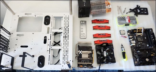
It’s time to get to the fun part: putting them all together.
before you kick off, you’ll want to set up a good work area.
Get some kind of table with plenty of room and light, preferably somewhere that isn’t carpeted.
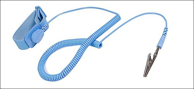
If your home or your workspace is particularly prone to static discharges, you might want ananti-static bracelet.
But if you want to be extra cautious, it couldn’t hurt.
(Or, if you have one, amagnetic parts trayis wonderful.)
First: Examine Your Case
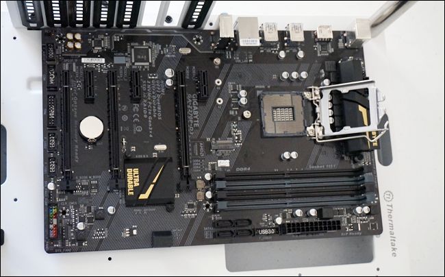
First, take a look at your case.
You might notice that the PC case we’re using in these photos looks a little strange.
Just imagine it with walls on an extra five sides.

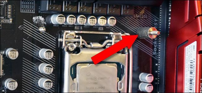
Raise the plate up, then take the CPU out of its protector.
This will correspond to a similar arrow in the socket, so just line them up.
When you’re sure you know which way the CPU fits into its socket, gently slip it in.
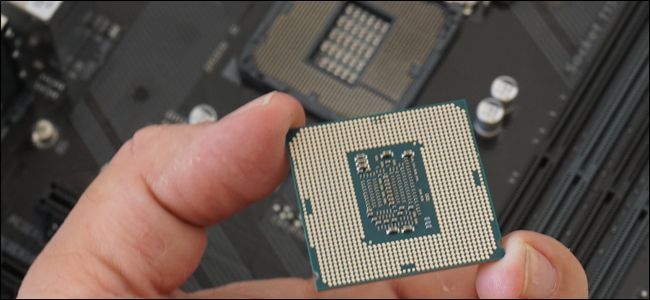
You should be able to let it go and it will simply fall the last millimeter or two.
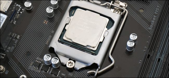
It should be flush with the walls of the socket.
Go back to the start of this section and start over.
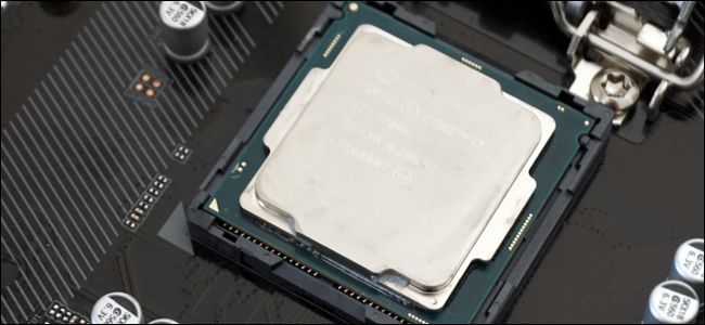
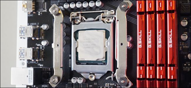
If you could lower the plate all the way, great.
Press the lever down beneath the safety tab.
You’re ready to go on.
Smaller boards might have only two, larger and more expensive boards can have as many as eight.
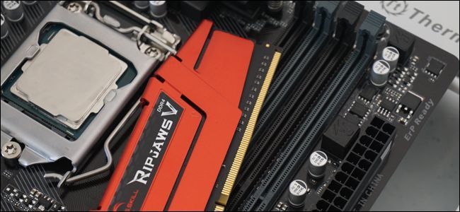
We’re going to be inserting four RAM sticks (DIMMs) in our build.
Take a look at your own DIMM and its corresponding slot.
If for some reason your RAM won’t fit, it’s probably incompatible with your motherboard.
Put the RAM in, contact-first, and press down firmly.
The clips should snap back into place to secure the DIMM.
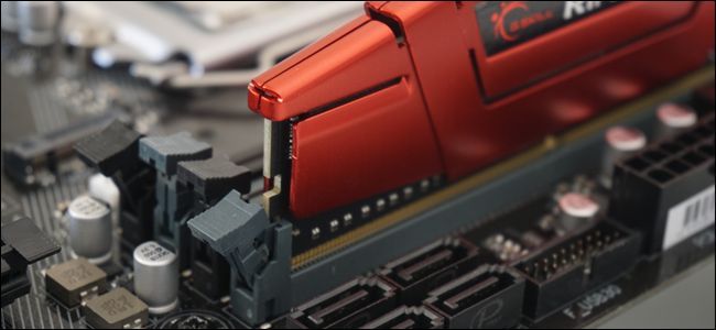
Press down on the RAM at the top and bottom to be sure.
Repeat the process for all the RAM modules you have.
If all of them aren’t parallel, push down until they are.
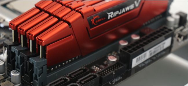
Notice how the slots in the photos above alternate colors, black and grey?
That’s because of the way they’re designed to work with memory channels going to the processor.
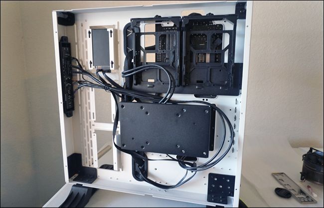
Remove the case’s access door and look down.
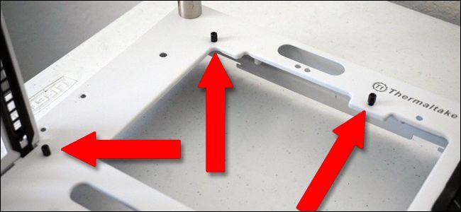
Our ATX-standard motherboard uses six.
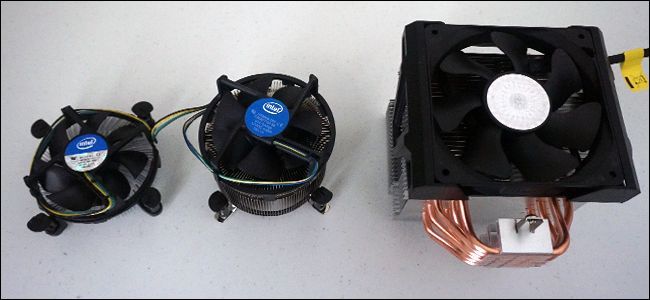
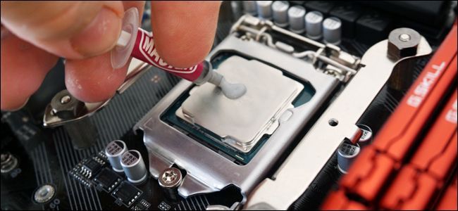
Stock coolers do not require this.
Before you place the motherboard itself in the case, roll out the I/O plate.

Make them good and tight, but not so tight that they crack the circuit board.
(If they’re already pre-installed in your case, you’re free to skip this step.)
Install them now so you don’t have to worry about the components getting in the way later.
Your case manual may have more information.
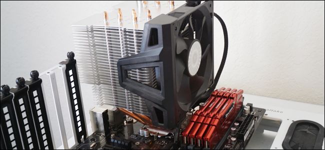
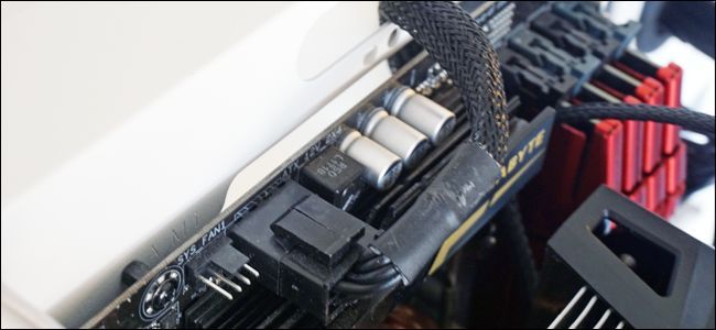
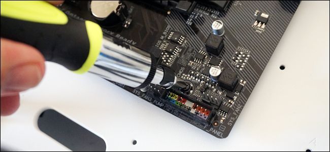
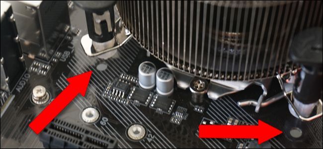
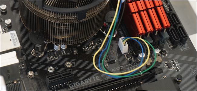
One the cooler is in place and secure, you’ll need to plug its power cable in.
There’s a small three- or four-pin power port on the motherboard, very close to the CPU socket.
Plug it in with the short cable to power the cooler’s fan.
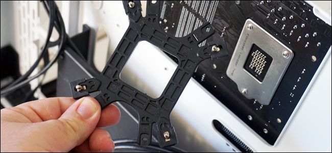
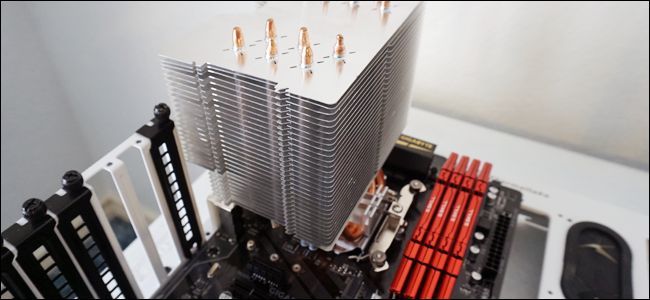
Assemble the backplate for the larger cooler.
set up the risers on the screws coming up from the cooler mounting plate.
Leave the rear panel removed, it will save you time later.
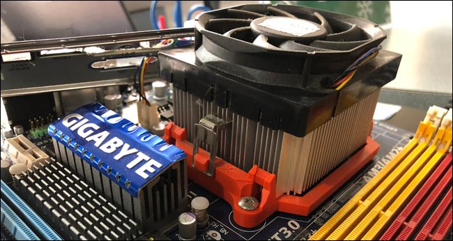
Continue to follow the instructions to install your specific cooler.
Finally, attach the fan onto the cooling fins (this may already be done for some coolers).
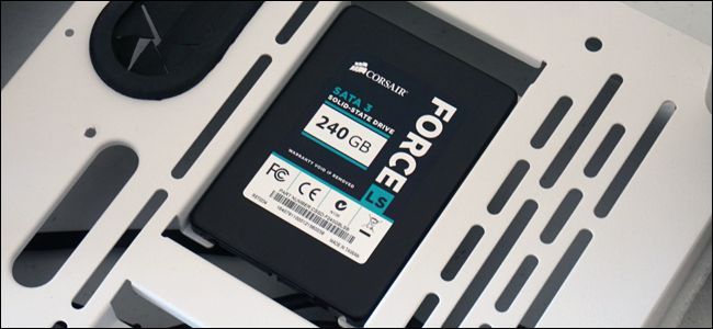
Either your case or your drive itself should include screws to secure it in place.
Check your case’s instruction manual if it’s not immediately obvious where your storage drives should go.
Our SSD drive goes in a little groove on the side of the case.
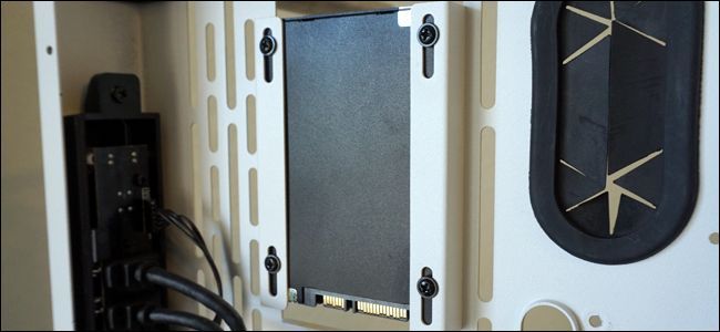
I raised the case to the vertical position again, then inserted and tightened the screws from the back.
(The case also has larger brackets for optional 3.5-inch hard drives, which we’re not using.)
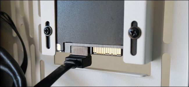
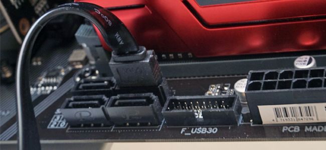
There’s only one way the cable can fit, and it’s the same connection on both sides.
Then, plug that same cable into the SATA port on the motherboard.
Repeat this process for as many SSDs or hard drives as you’re planning to use.
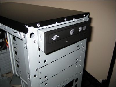
Installing a DVD drive, if you have one, is also pretty simple.
Like the caddies for SSDs and hard drives, this just makes it easier to take replace the drive.
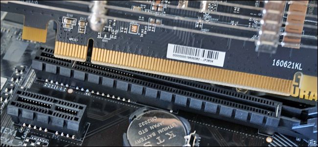
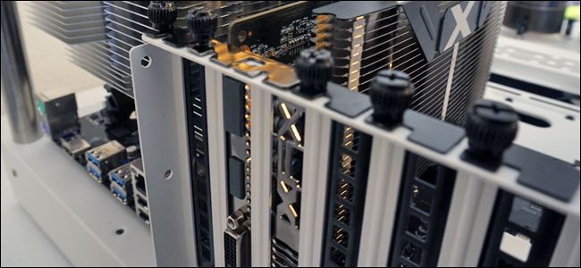
Related:Why Are the PCI Express Ports on My Motherboard Different Sizes?
If this stuff is confusing, check outthis article on using the right PCI-E accessories in the right slots.
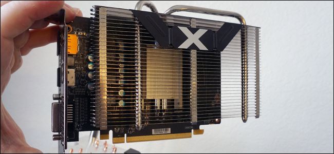
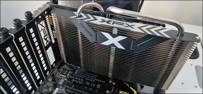
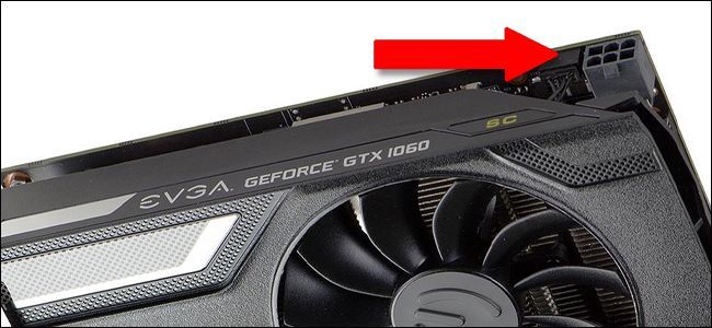
Slide the graphics card in, starting with the side closest to the outside of the case.
Press firmly down until the tab locks into place.
Then, put the thumbscrews back in where they came from, securing the card in place.
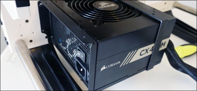
Step Eight: drop in the Power Supply
You’re getting close to the end here.
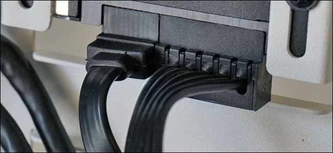
Slide the power supply into its bay or bracket.
Sometimes you may need to screw the supply in place via the holes on the outside of the case.
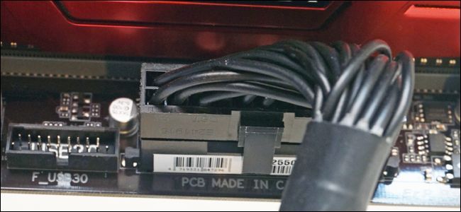
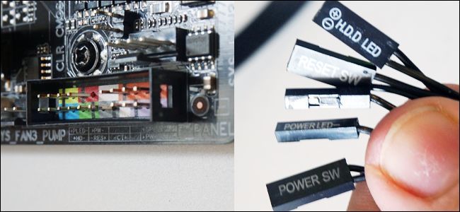
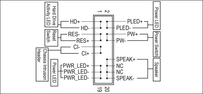
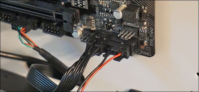
This panel is usually at the bottom-right of the board.
Some or all of these might be broken into positive and negative connectors.
These get frustrating because they’re tiny and hard to read.
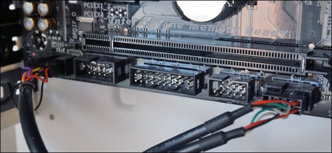
It’s best to break out your motherboard’s manual and look for specific instructions on the I/O panel.
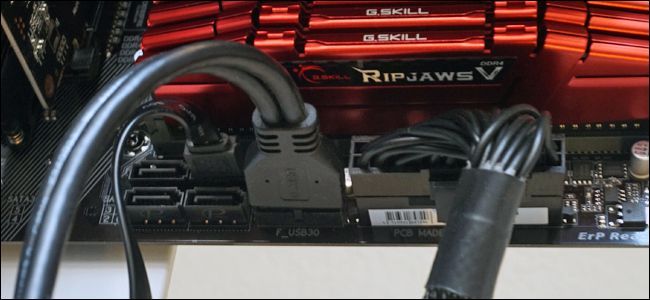
The bigger plastic cable for the USB 3.0 jacks goes in the side.
Wrap It All Up!
You’re nearly done.
Then put the front and rear covers on and secure them in place with the thumbscrews.
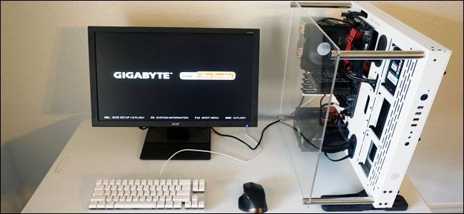
Plug in the power cable to the power supply, then your monitor, keyboard, and mouse.
Press the power switch.
Congratulations, you’ve successfully assembled your PC!
Or, if you want to jump to another part in the guide, here’s the whole thing: